Mobilisation
Mobilisation of the equipment onboard the R/V Urania was carried out on the 3rd March 2009 while alongside Bari, Italy and on 4th March 2009 while at sea. The equipment consisted of Seal system 5 with a high reso- lution (HR) 96 channel 12.5m group length streamer supplied on the NiM winch with integrated hydraulic pack. Additional equipment which we sup- plied was dual NAS drives for data storage, FSK/Digicourse (DOS) bird (leveller) controller and Sercel eSQC Pro and iSys V12 plotter for online quality control (QC) of the data. A full complement of spare for all of this equipment was also supplied. The winch was welded (using sacrificial angle iron supplied by the ship) to a frame on the back deck which normally supports the clients own winch. All of our electronics equipment was setup on our bench in the ships dry lab. Birds were stored in the wet lab when the equipment was onboard. Navigation were situated directly behind us and the gun control was directly to our left. The compressor manifold pressure could be observed from a remote display.
Networking and Interconnection
The normal Seal configuration with Seal workstation, CMXL (recorder) and NAS servers on the 150.10.128.x network and just the Seal workstation and eSQC Pro on the 172.27.128.x network was used. In addition the Seal network hub was connected to the ship's network. The connection to the ships network was for two purposes. Firstly it allowed the data to be copied real-time (actually with a short delay since the data transferred once every 5 minutes or so) to the clients central NAS. This was achieved by the client running 'rsync' which just copied any files that had been added or updated since the last time it was run. This was scheduled by adding it to the cron table. The second purpose was to allow the Seal system time (and also the NAS server time) to be synchronised to the ships server (GPS accurate) time at regular intervals using 'ntpdate'. The CMXL was triggered from the gun controller by a TTL pulse. We tried to record a navigation string (with the usual information such a shot number, lat/long, time, etc) onto the SEG-D header by connecting by RS232 and UDP to the CMXL but by both methods this was unsuccessful because the navigation system was not able to delay before sending the string. The Seal requires that a short delay (typ. 50ms) is left after the trigger before the string is sent. Limited success was achieved but always the beginning of the string was missing.
Parameters and Offset Diagrams
Due to the nature of the project the various parameters were changed many times during the project. To keep track of these changes the important parameter are outlined in table 8. See the main observer log (.pdf format) for detailed information. The sheet numbers in 8 refer to the sheets in the main observer log file.
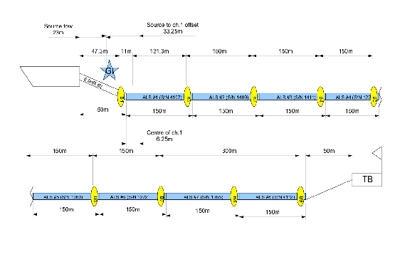
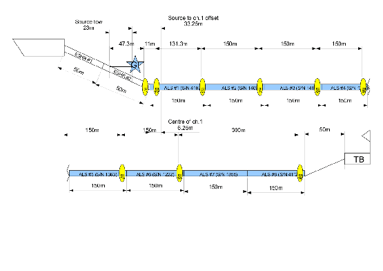
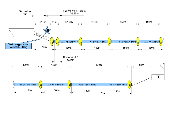
Since the offsets and bird positions were changed three offset diagrams were included. Figure 31 describes the setup for sheets 1-3 (inclusive), Figure 32 is for sheets 4-8 and Figure 33 is for sheets 9-23.
figure
figure
figure
Table 9 indicate the positions of the birds and which streamer channel they were closest to since this will be the channel most infuence by the turbulence they induce. The auxiliary channel setup is shown in table 10.