


Next: CTD CASTS
Up: PRELIMINARY RESULTS
Previous: PRELIMINARY RESULTS
Contents
During the cruise 23 multichannel seismic lines were run (Fig.3 and 4. The acquisition parameters are presented in table 7 in Appendix, as long as the shot-depth plots.
One of the processing challenge is to remove the unwanted direct-wave, that is several orders of magnitude larger than the backscattered energy from the water structure. This is especially important for this cruise where the targets are at shallow depths. The raw data, digitised and stored in SEGD format (www.seg.org), are reformatted the to 32-bit floating point, using a 'segdread' programme provided as part of the Seismic Unix package. The modification was made to work specifically with a similar Exploration Electronics Ltd SEAL recording system that was previously used for the GO-project.
figure
Figure 14:
(LEFT) : Raw seismic shot. (RIGHT) :Shot gather after low cut filtering to remove sea-surface noise and time shift to align time zero with shot fire instant.
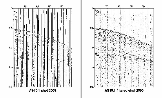 |
Figure 14 shows a raw shot record. The vertical axis is two-way travel time (1.0s is approximately 750m), the horizontal axis is receiver channel number with channel 1 closest to the stern of the vessel and channel 96 furthest from the stern. The group interval between channels is 12.5m. The unwanted direct wave is the linear event starting at about 0.1s at channel 1 (see Fig.14). The seabed reflection is the hyperbolic event starting about 0.55s at channel 1. Between the two lie the required weak water column reflections. The pervasive low frequency energy is caused by pressure changes at the hydrophones caused by surface waves.
During the cruise we tested several configurations. In particular we tested: (a) minimizing the source/receiver offset as this directly effects the minimum depth that can be vizualised after processing; (b) seismic source configurations to show that seismic oceanography can be achieved with a one or two airgun source and does not require use of large arrays and a dedicated ship configured for seismic reflection work (however this will only be successful if the impedance contrasts are strong); (c) effect of tow depth of streamer on vertical resolution (this was compromised by inherent ship noise - see below).
The processing of the data then follows a consistent path:
- (1)
- convert segd to su (seimic unix internal 32-bit floating point format)
(Fig.3)
- (2)
- remove any dc shift from traces
- (3)
- 0.01 s ramped mute at start of trace to minimise filter artefacts
- (4)
- minimum phase 10-20Hz low-cut filter to remove sea-surface wave noise
(Fig.4)
- (5)
- impose geometry assuming no cross-line deviation of streamer (for the
profiles the maximum cross-line error just over 200m at an offset of 1200
m) and assign CDP bins of 25m for stacking
- (6)
- apply a time dependent gain
- (7)
- subtract a median filtered trace (length 7 traces) to suppress the
direct wave (Fig. 5)
- (8)
- remove the time dependent gain
- (9)
- sort to common mid-point gathers using previously assigned CDP bins
apply normal moveout correction (NMO) with constant velocity (1514m/s) with
a stretch mute set to 200
- (10)
- stack data with 1/N normalisation (N being number of live traces which
depends on effect of previously applied stretch mute)
- (11)
- post-stack Gaussian weighted 7-trace mix (effective œ width of 3
traces)
- (12)
- post-stack minimum phase band-pass filter low-cut 10-20Hz high-cut 60-
100Hz
- (13)
- final display with gain level set to visualise water structure (Figs. 7
and 8).
figure
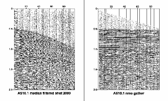
Figure 15:
(LEFT) :Shot gather following median filter to suppress direct wave. Note some residual energy on the nearest offset traces. These traces are removed prior to stack. Also gain of section increased to show events in water layer. (RIGHT) : Gather after normal moveout correction to align sea-water reflections in time prior to stack. (Vnmo=1514m/s). Note this sound speed is not correct for sub-seabed reflections and reprocessing to image sub-seabed structure will require detailed velocity analysis.
 |
NOTES:
- (1)
- on-board processing using the Seismic Unix package
- (2)
- segdread programme modified by GO-project (Hobbs & Klaeschen)
- (3)
- median filter modified by Hobbs
- (4)
- source/receiver offset varies according to profile (see observer logs)
- (5)
- streamer depth varies according to profile (see observer logs)
- (6)
- gun configuration varies according to profile (see observer logs)
During the cruise it was noted that there was a strong interference of noise with apparent moveout similar to the required reflections. Investigations showed that the ship had a natural vibration centred on 150Hz with significant energy between 120 and 180 Hz. We tested different configurations of seismic recording system to a better use at shallow imaging of water structure (<500 m) and also for deeper targets (>500 m, e.g. Bari Canyon), where the system used during this cruise is ideal.
figure
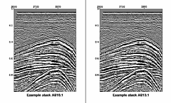
Figure 16:
(LEFT) : Section of final processed seismic profile from near the Bari Canyon. The horizontal scale is by shot-point number where the shot spacing is 18.75m. So 100 shots equals 1.875km. The vertical scale is two-way travel time where 0.2s = 150m (assuming a sound speed of 1500m/s). The seabed is the strongest refection with the typically two or more distinct events in the water layer. With the filters imposer during processing the vertical resolution of the section is about 10m so any significant gradient in sound speed * density (impedance) will create a reflection. (RIGHT) : Second example of seismic image showing coherent reflections close to the sea-bed and also at a depth of 37 m at shot point 1250.
 |
Next: CTD CASTS
Up: PRELIMINARY RESULTS
Previous: PRELIMINARY RESULTS
Contents
2009-12-16