The survey was planned and executed at an average speed of 10 knots. Positioning was accomplished through differential GPS RACAL-Skyfix with corrections from the station based in Rome. The DGPS data were routed to the multibeam console and to the ship's logging and steering complex through Trimble HYDRO PC and Trimble 4000DL GPS sensors. The HYDRO navigation data were stored as binary files with a sampling rate of 10 seconds, to be converted ASCII offline. The multibeam navigation data were stored by the Simrad software MERMAID on the ships's logging workstation with a sampling rate of 1 second. The HYDRO navigation data were used for the integration with the russian magnetic and gravimetric data, thus obtaining for this dataset, the same sampling rate of 10 seconds. The seismic and italian magnetic data were recorded on a separate PC-based workstation, with a sampling rate at constant spacing of 50 metres. This latter workstation was served by a Trimble 4000 GPS. The data were then merged with the high-quality DGPS data and with the Multibeam and HYDRO data by correlating with the GMT date and time for all acquisition sytems.
The Navigation System had the following major settings:
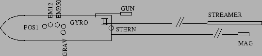
Tab. 3 and Fig. 5 show the offsets of principal instruments. It is worth to note that on Multibeam files the POS 1 position is recorded, as well as on the other instrumental binary and ASCII files. That is, the final coordinates for every instrument have to be recalculated accordingly.
figure