next up previous contents
Next: Setting of the AcutimeTM Up: DAPHNE_REPORT Previous: Bibliography   Contents


Connection of the AEP Load Cell

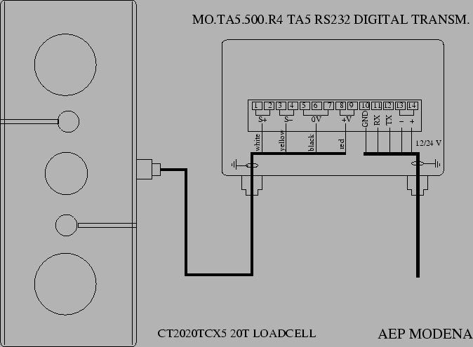
Fig.20 shows the electrical connections of the T20 Load Cell to the TA5 Digital RS-232 Transmitter. The system was installed with a data cable length of aproximately 45 m (from the stern A-frame to the recording room. The system worked fine with a power supply of 12.5V. However, 24 V should be preferred if available.

Figure 20: Electrical connections of AEP's T20 Load cella to TA5 transmitter.
\begin{figure}\centering
\epsfig{ file=IMG/AEP_T20_TA5.eps,width=15cm}
\end{figure}


2004-03-24