The INGV and TECNOMARE SN-4 observatory was developed in the framework of ORION (Ocean Research by Integrated Observatory Networks) EC project and deployed as node of ASSEM (Array of Sensors for long-term SEabed Monitoring of geohazards) EC project during a joint experiment in the Corinth Gulf (Greece, 400 m w.d.) in 2004 [Favali & Beranzoli, 2009], proving compatibility of GEOSTAR-class observatories with other networks. In its first configuration SN-4 was based on a light frame whose main characteristics are summarised in Table 1.
All sensors installed on the observatory are managed by dedicated low-power electronics, able to perform the following tasks: (a) management and acquisition from all scientific packages and status sensors; (b) event detection; (c) preparation and continuous update of hourly data messages; (d) management of bidirectional communications via hydro-acoustic telemetry link (including transmission of seismic wave forms); (e) actuation of commands received (e.g., data request, system reconfiguration, restart) and (f) complete data back-up on internal memory. The SN-4 electronics can manage a wide set of data streams with quite different sampling rates tagging each datum according to a unique reference time set by a central high-precision clock.
During its first mission in Corinth Gulf SN-4 was equipped with a 3-C broad-band seismometer, an hydrophone and a methane sensor, with one year autonomous operation with 12-V, 960-Ah lithium battery pack. To reduce disturbance of the frame and electronics, special devices were designed and implemented for installing the seismometer, which is lodged in a dedicated vessel integrated in a separate structure connected to the SN4 by a special mechanical release. To guarantee a good coupling with the sea bottom, the structure is disconnected just after the touch-down and kept linked to the frame by a slack rope. This method of seismometer installation proved to record higher quality data during all the GEOSTAR-class observatory missions.
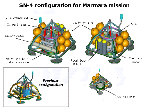
For the Marmara mission the configuration of the SN4 was modified, aiming at better quantifying the temporal relations between fluid expulsion, fluid chemistry and seismic activity along the NAF. The new payload and relevant sampling rates are summarised in Tab.4. The station will be deployed using ship's winch and an acoustic release like in ASSEM mission, but the recovery procedure was redesigned, i.e. station will be recovered by a rope released by an acoustic command, letting the operations be performed by ship-of-opportunity. To achieve this result, the total weight in water was reduced to 0.15kN (![]() 150 kg)from the 500kg in air by installing 8 benthospheres on the frame and adopting new lighter vessels for batteries and Electronics. This new fitting will make recovery and redeployment eeasier at the end of scheduled 6 months of activity . For future applications, SN-4 can be re-configured to operate as cabled observatory for permanent long-term real-time monitoring of the Marmara Sea to study relationship between fluids and seismicity.
150 kg)from the 500kg in air by installing 8 benthospheres on the frame and adopting new lighter vessels for batteries and Electronics. This new fitting will make recovery and redeployment eeasier at the end of scheduled 6 months of activity . For future applications, SN-4 can be re-configured to operate as cabled observatory for permanent long-term real-time monitoring of the Marmara Sea to study relationship between fluids and seismicity.
INGV SN-4 is a multidisciplinary observatory, designed and built in cooperation with Tecnomare. It can support on-demand payloads and it is based on technical solutions developed for INGV Geostar-class observatories (>4000 days of operation, 13 missions, up to 3320 m water depth). Its original seismometer management procedure, allows SN-4 to be re-configured to operate as cabled observatory (using a simple and cheap electrical umbilical cable, with cost in the order of few E/m).
The configuration for the ESONET Marmara Mission (Fig.5) is as follows:
figure