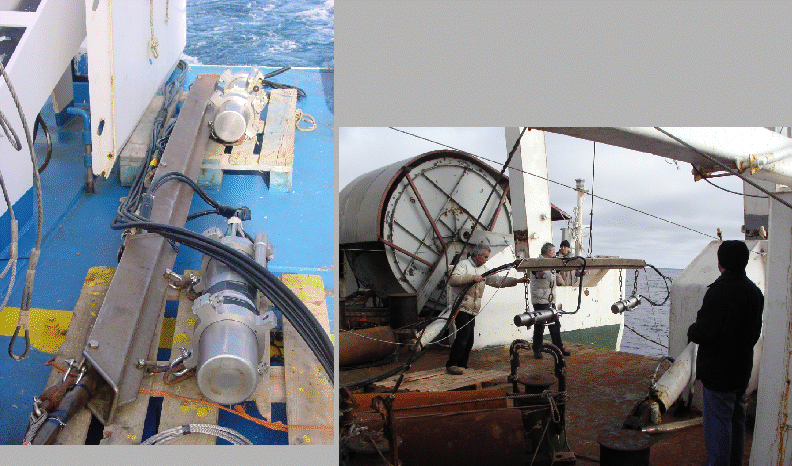
High-resolution multichannel seismic were performed by ISMAR using an array of two
synchronized SERCEL (formerly SODERA-SSI) GI-GUN (Fig.18),
(in the 105+105 c.i. Harmonic configuration) pneumatic sources, powered by
two 2000 L/Min, electrically driven air compressors.
The pressure to the gun ranged from 130 to 180 bars, depending on speed of profiling
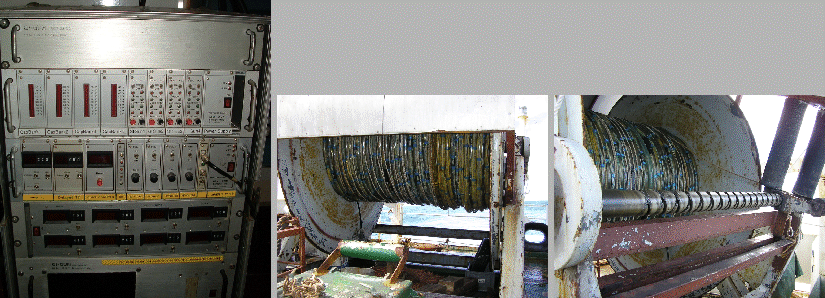
and compressor's delivery. The seismic data were collected by a MOD.29500 TELEDYNE 48
channel streamer (Fig.19), digitized and recorded on DDS-1
and DDS-2 DAT tapes by a OYO-GEOMETRICS's STRATAVISOR seismograph in the SEG-D
8048 Revision.0 format, with sampling rate of 1 msec and record lengths of
12+ secs.
The group interval was of 12.5m for a total active length of 600 m. The 100 m
tow leader, two 50 m stretch sections and tail rope made up the streamer to a total length
of 900 m. The seismic source was fired by IGM's gun-control
equipment [Masini and Ligi (1995)] (Fig.19) that introduced a fixed delay of
10 msec from the time break. The injector delay was set around
44 msec ![]() 2 msec according to pressure delivered by compressors. The guns were automatically synchronized
by adding delays ranging
2 msec according to pressure delivered by compressors. The guns were automatically synchronized
by adding delays ranging
![]() 0.5 msec to the near gun. An additional delay of 15 msec to the above figure had also to be added
due to the opening of electrovalve, thus reaching 25
0.5 msec to the near gun. An additional delay of 15 msec to the above figure had also to be added
due to the opening of electrovalve, thus reaching 25 ![]() 0.5 msec from the time break.
Shot distances were of 50 m, thus achieving coverages of 600%.
The time break was provided by the seismic module in the NAVPRO software,
with the DISTANCE FROM PREVIOUS SHOT setting, in order to maximize the
survey flexibility allowing the SHOT NOW capability when enroute.
The depth of the source ranged between 5 and 7 m depending on sea state.
The streamer was kept at 10-12 m depth with SYNTRON RCL-2 cable-levelers,
using a Teledyne Mod. 28951 depth control system.
0.5 msec from the time break.
Shot distances were of 50 m, thus achieving coverages of 600%.
The time break was provided by the seismic module in the NAVPRO software,
with the DISTANCE FROM PREVIOUS SHOT setting, in order to maximize the
survey flexibility allowing the SHOT NOW capability when enroute.
The depth of the source ranged between 5 and 7 m depending on sea state.
The streamer was kept at 10-12 m depth with SYNTRON RCL-2 cable-levelers,
using a Teledyne Mod. 28951 depth control system.
The data were processed onboard using the DISCO/FOCUS packages by PARADIGM, up to the time-migration of some sections, using a standard processing sequence.
An offset of 106.5m between the source and the first active was found by measuring the time distance on the sections, subtracting the 25 msec delay, converting to distance by using value of 1466 m/s.
figure
figure
 |
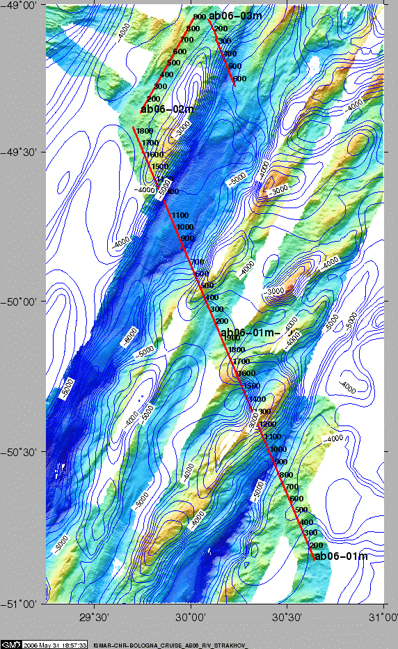
The runlines can be shown in Fig.20.
figure